
Domače Volt Orkester seeks to re-purpose discarded technologies to create instruments and installations of new wonder. The detritus of domestic electrical goods can be given a new life, a new ‘stage’ on which to ‘perform’ afresh for us humans, or even just for themselves.
It was developed in Interactivos 12´ in Ljudmila

Domače Volt Orkestra does not breathe new life into old radio's, vacuum cleaners and tools. It simply misuses them. It directs there 'use', their capital and commercial productivity to a completely 'useless', and 'un'-valuable purpose. Namely making a live, low-verging-on-no-tech audio-visual experience.
DOMAČE VOLT ORKESTER from Juan Duarte Regino on Vimeo.
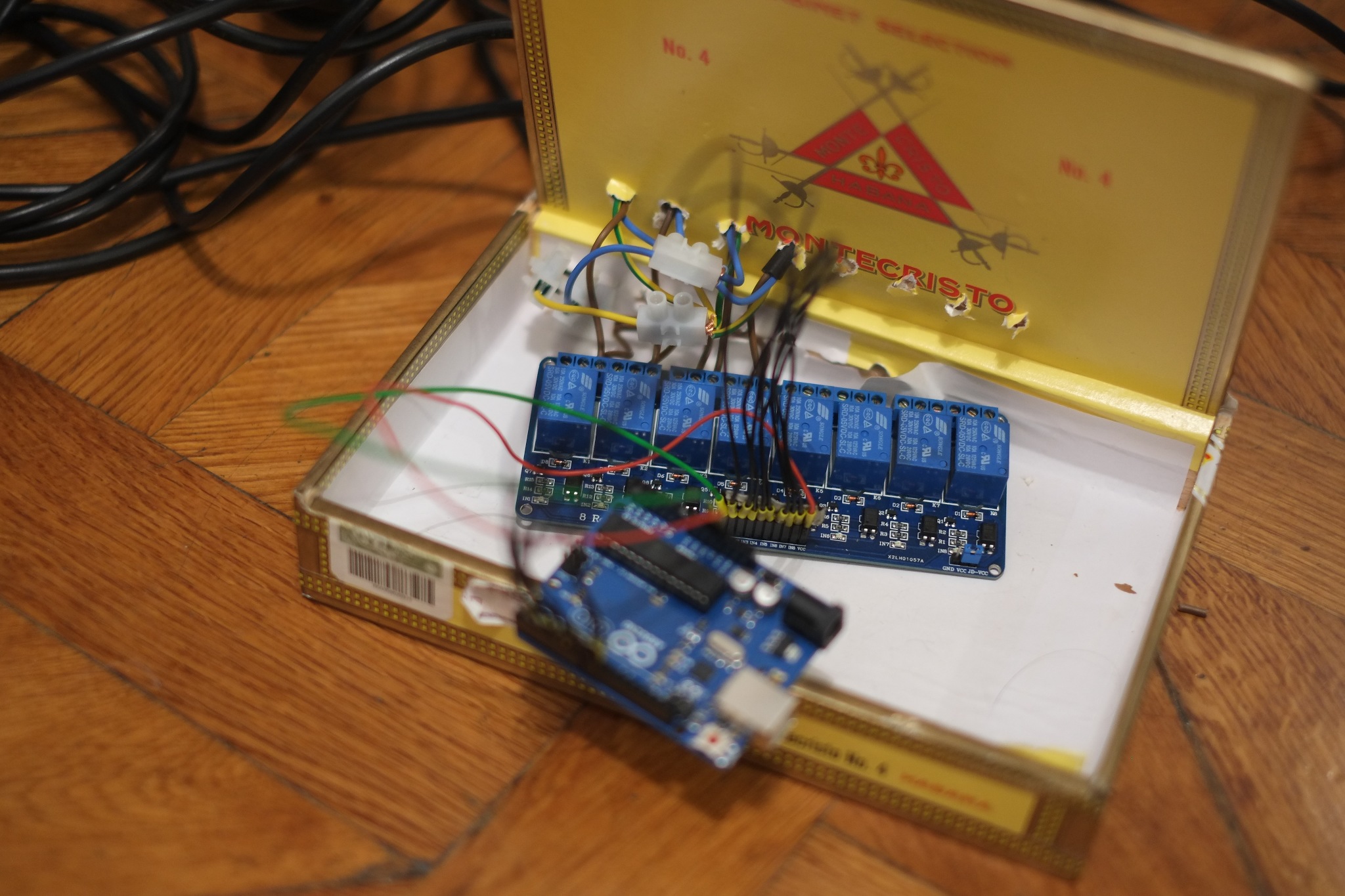
Since we used opto-isolated, magnetic relays (an arguably obsolete technology) Project's operative principle is based on a relay to Arduino system. The process of collaboration was open as possible, to explore their own take on the overall concept. As such we split up into 3 co-operative splinter groups:
1) The Relay-Arduino-Communal-Sequencer
One PC acts as a Server, which accepts commands that modify the sequence, changes the output to the instruments, and broadcasts the changes in the sequence to the other users so that every one has real time updates. Upon startup, each client opens a UDP connection with the server, and uses a special message format to communicate which sequencer button is toggled and when.
The server receives the commands from the clients, and stores the state of the sequencer that it steps through at a given tempo. Each sequence is divided into a certain number of states, corresponding to the period of the sequence (i.e. the time a single pattern is performed before repeating), and a number of channels, corresponding to the number of attached instruments.
Each channel is either a relay (for which each state is either ON or OFF) or a dimmer (for which each state is a value between fully on and fully off). At each state change in a single channel, the server sends a serial message to change the activation of the attached instrument.
The relay boards are electromechanical 240V 50Hz relays controllable though 5V logic. They make a magnificent 'click' every time it opens or closes.
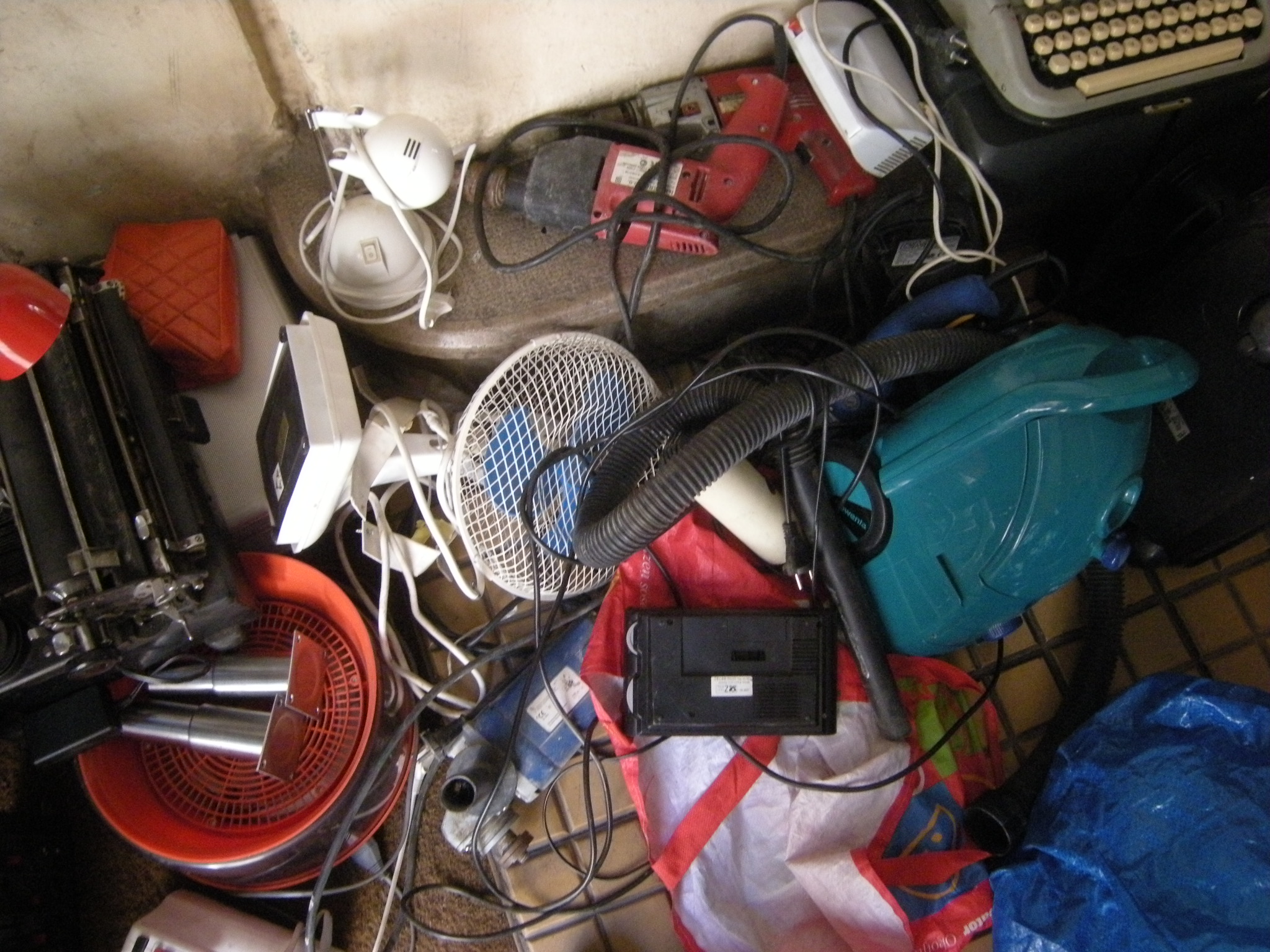
The attached devices are the instruments and in principal, they could be anything that runs off of wall AC power (up to 250V, 10A). For our Interactivos performance, we are using clock radios, blenders, massagers, power drills, incandescent light bulbs, electric shavers, vacuum cleaners, a water pump, a printing calculator, angle grinders, and a paper shredder.
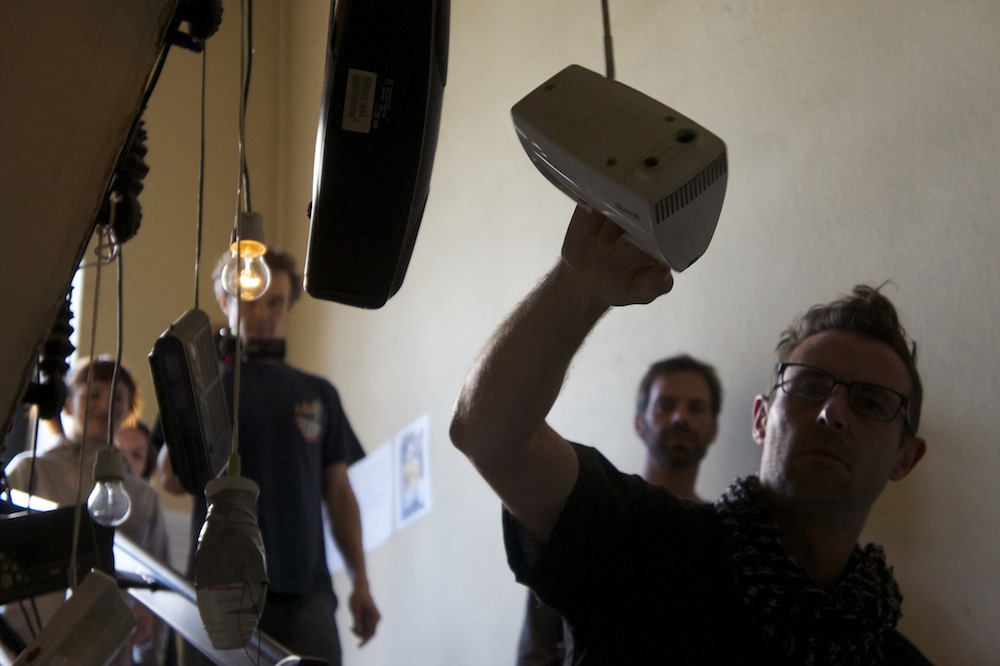
For our Ljudmila-stairwell installation/concert, we installed four 8-channel relay boards and two 8 channel dimmer circuits, for a total of 48 channels. Each one had to be wired individually to a channel on their respective dimmer or relay boards. (NB: though we had the capacity to wire even more devices to up-to 7 relay boards and 2 dimmer circuits for a total of 72 devices, due to total power consumption per board, cable limitations, and a general paranoia from outside agitators we were forced to leave some relay and dimmer channels unoccupied.)
Domače Volt Orkester. Interactivos´12 from Ivan Arroyo on Vimeo.
2) The Piezo-Transducerfier-Amplifier-DSP
The amplification is a complementary element of orchestra to boost the resonance from ulterior vibration of motors. For this purpose a set of custom made amplifierspiezo microphones was built so that can be attached to domestic appliances. The signal of these microphones is processed with Pure Data patches to generate a sound environment with long decay drones, and sub harmonics.
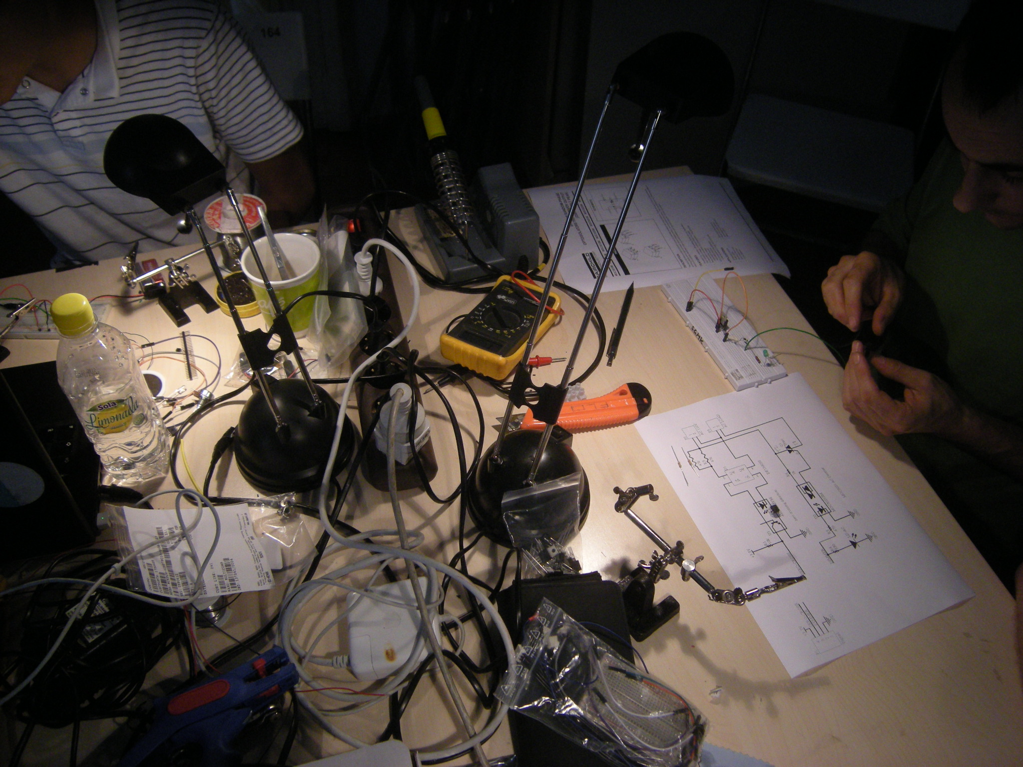
We tried a variety of piezo microphones that were prototyped in breadboard until they became an end shape circuit. In this sense it was very useful to work on the schematic of Nano Amp provided by SGMK group.
The realization of the amplifier circuit implied to understand the operative logic of LM386 chip. This 8 pin chip is internally set to 20 to keep external part count low, so It is possible to have addition from external capacitors (220 uF and 10 uF) to amplify the signal received from the piezo microphone.
Therefore it was a learning process to understand the relation between the electronic elements. Likewise the soldering the final circuit requires a patient and carefully work that makes each part connect into their right place. It was noticed which objects were relevant as minimum requirements to amplify the signal, or control as a variable the resistance and capacitor functions.
There is a number of sound modules for DSP (Digital Signal Process) which consist in a granular synthesizer, a phaser envelope, a spectral delay and a loop generator. The input parameters of this sound modules will come from the controls of relay and fading group.
For future development there will be a different approach to control electromagnetic fields that trigger sound devices.
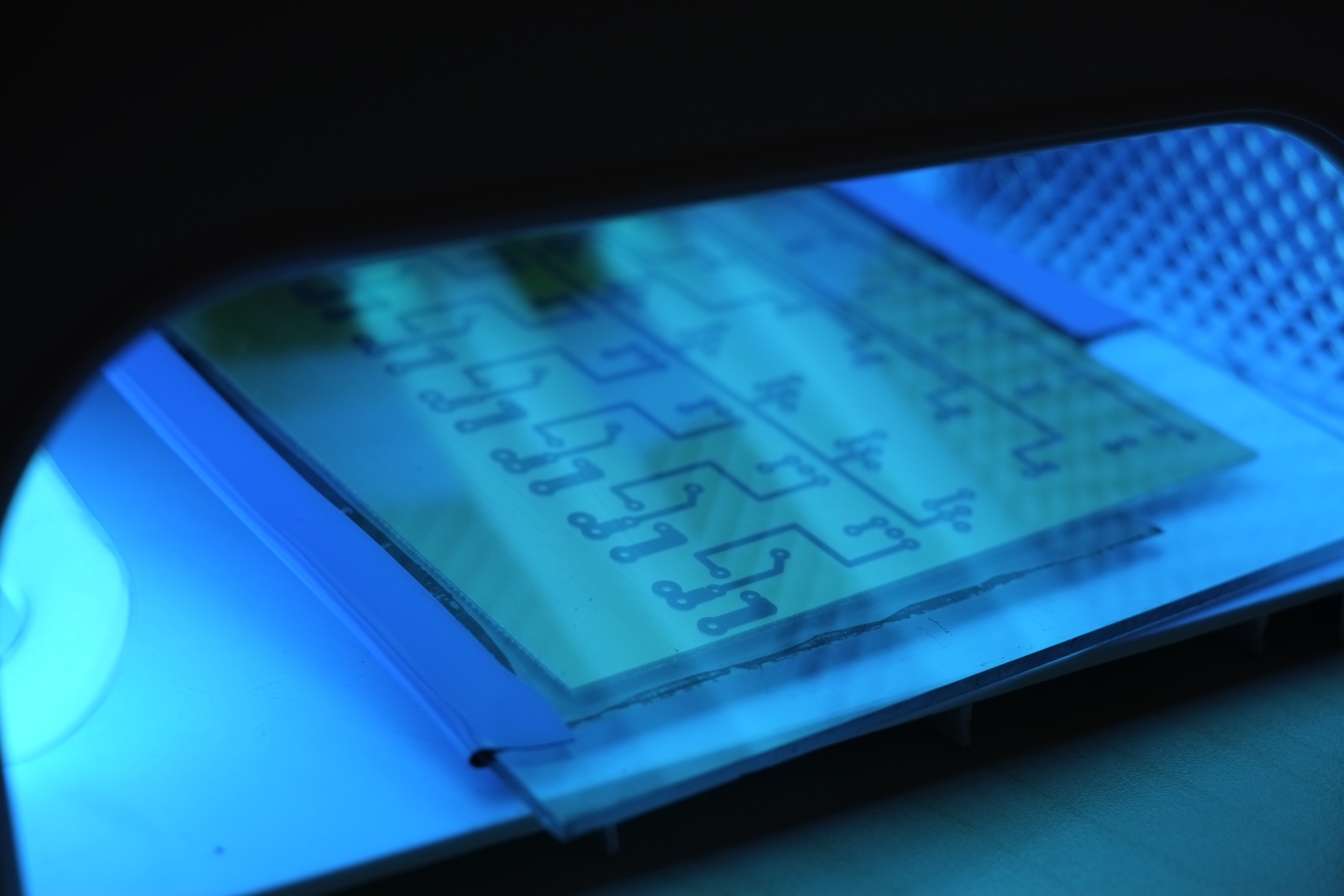
3) The Low-Cost-240v-Dimmer, later to become the N-1-Less-Wire-Dimmer
The aim was to be able to regulate the speed of motorized gear and incandescent lights used in the installation.
After testing the board as was proposed initially, some variations have been made to the original:
-we were using BT138600E for the triac, and the rectifier DF15005S was overridden by W10M.
- we maintained one circuit for zero-crossing detection, and replicated the circuit of the dimmer control to obtain a 8 channels layout.
- the 47K resistors had to be 2W. Otherwise the temperature would get above 130ºC. We were actually using four 100K (2W) resistors in parallel.
A drawing for PCB developing, and schematic, have been made, and are now available as a pdf. Two PCBs have been printed, components soldered, and wiring made into two separate boxes. One of them will be driven by an Arduino UNO board, and the other will be operated remotely through an XBee board. An Arduino sketch has been coded, where the zero-crossing interrupt was detected and each of the triacs trigger programmed. The sketch had to be adapted to 60Hz/50Hz, and to the speed of the processors clock. Indications for these adjustments were found inside the sketch. We have limited the total AC load of the board to 2KW, and of each of the channels to 500W.
With Matthew Gingold (Australia) and Ben Olsen (USA) Iván Arroyo (Spain) and Martina Kalogjera (Croatia).